Understanding Two Critical Principles of LiDAR Data Acquisition
If you are familiar with any type of LiDAR data acquisition, you have likely stumbled across terms including ‘boresight calibration’ and ‘strip alignment’ (or strip adjustment). These terms relate to separate strategies for adjusting and aligning adjacent strips of aerial LiDAR data. In this blog (first in a two-part series), we will address why boresight calibration and strip alignment are important considerations for UAV-LiDAR missions. In part two of this series, we will provide practical information to the LiDAR end-user which further addresses and explains the points raised in this blog.
Boresight calibration and strip alignment are particularly prevalent for UAV-based LiDAR solutions such as Geo-MMS LiDAR. UAV-LiDAR is acquired through many parallel ‘strips’ of LiDAR which overlap adjacent strips slightly (< 10%). The purpose of boresight calibration is to correct for minute misalignments between adjacent strips noticeable in the raw point cloud.
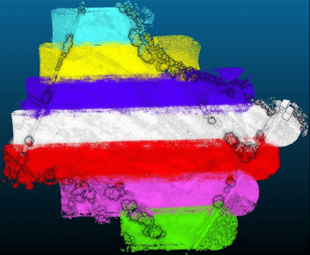
Figure 1. Flat terrain, captured across seven parallel UAV-LiDAR flight lines.
The main concerns for the LiDAR end-user are:
- Do we need data processing procedures to adjust our point clouds for possible misalignments?
- Is additional software needed to make these adjustments?
But first, we should address what causes these misalignments in the first place. Once the error sources are identified, we can better understand the principles behind LiDAR boresight calibration and strip alignment. When looking at the error budget of any aerial LiDAR system, we experience both systematic and random errors. With correct system calibration, systematic errors are removed and random errors are minimized.
Systematic errors result in the systematic deviation of laser footprint coordinates. Integration of Geo-MMS LiDAR or Point&Pixel payloads on your drone requires the axis of the scanning reference coordinate system and inertial platform reference coordinate system to be parallel. While physically mounting the payload to the UAV, it is not guaranteed that they will be parallel (human hands are not precision instruments). This results in what we term boresight error.
Figure 2 below summarizes the geometry of different components in the Geo-MMS system in a simplified vector-based visual. Once the LiDAR sensor fires a pulse measuring the range from the laser to the scanned feature, , we need three more observations to georeference the captured point:
- The position, provided by the GPS () and represented in the PPK solution
- The leverarm offset to transform the GPS position to the IMU center, marked as ()
- The boresight shift to transfer the position from the IMU center to the LiDAR sensor center, marked as ()
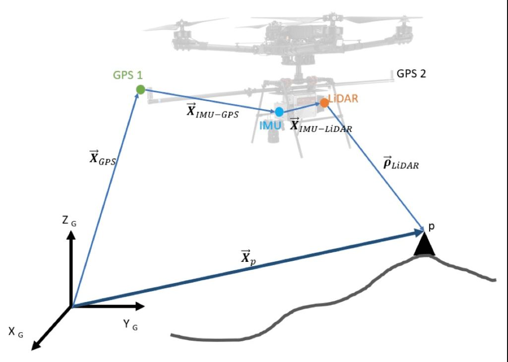
Figure 2. Direct georeferencing geometry
From vector geometry, the global position of the point, can be determined by adding the sequences of four vectors:
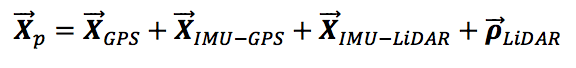
In this geometry reconstruction, we consider the translation between the components. Besides translations, the rotation between these components is critical. Considering the rotational influence at different sensor frames, Equation (1) can be rewritten as:

- represents the rotation matrix, reconstructed based on the roll, pitch, and yaw of Geodetics’ Navigator (INS)
- represents the rotation matrix from the IMU to the LiDAR, represented as the LiDAR boresight angle
Now that we have covered the basic geometry, we can highlight the main contributory points that direct georeferencing has on practical LiDAR usage:
- refers to the GPS-to-IMU leverarm This is a known calibrated value and is pre-configured with your Geo-MMS system.
- refers to the IMU-to-LiDAR offset or LiDAR boresight shift. This too is a known calibrated value and is pre-configured with your Geo-MMS system.
- refers to the LiDAR boresight angle. This too is pre-configured with your Geo-MMS system.
- refers to the PPK solution of the GPS antenna.
- refers to the INS-based rotation. This is determined by the INS (roll, pitch, yaw) and its accuracy is typically a function of the IMU grade, dual-GPS based heading and filter-tuning procedures.
The boresight error between the LiDAR sensor and the onboard GPS/INS coordinate system is the largest systematic error source in UAV-LiDAR. The laser footprint error produced as a result of boresight error is also impacted by flight altitude (AGL) and scan angle.
The main purpose of this geometry breakdown is to highlight the five most important variables which directly impact the quality of the LiDAR data generated. Among these variables, two cannot be pre-calibrated: PPK solution and INS attitude. Several algorithms are implemented in Geodetics’ LiDARTool software to improve the PPK and INS solutions including forward-backward PPK smoothing and rounding point coordinate values to fine resolution grids. However, leftover errors can still impact point cloud reconstruction quality in harsh environments.
In part two of this series, we will more closely examine the questions posed at the beginning of this blog, pertaining to the two main concerns of the LiDAR end-user.
Have questions? Contact our team today for a discussion on the points raised in this blog!
Already confident you know the best hardware and software solution for your projects? Request a Quote today!
