A Quick Guide for your Mobile LiDAR or Photogrammetry Mission
Base station placement for aerial or ground based mobile mapping projects is one of the most critical factors to consider for successful PPK-RTK processing. Given the number of variables involved in enhancing navigation solution quality for such projects, base station location may seem like a trivial matter. However, the choice will determine the quality of output of the entire workflow. There are several factors to consider when it comes to choosing the base-station location. This blog assumes the reader is already familiar with the basic principles of RTK-PPK processing. These are covered in an earlier blog titled Do you Need RTK for your Geo-MMS UAV Mapping System?
Highly accurate GPS positioning requires more than five common satellite measurements (observations) between the Geo-MMS mapping payload GPS (rover) and the base station. More satellite observations yield improved navigation accuracy. Accuracies at the cm-level are typically provided when both base and rover have visibility to more than six satellites. Ideal base station placement is thus determined by selecting a site for the base station that is close to your mission (i.e. <10 km) and that provides a clear line-of-sight between the base station and orbiting satellites.
Figure 1 below illustrates several options for the placement of a base station. In this example, let’s assume that an accurate PPK solution is needed for a UAV-based Geo-MMS mission. For any UAV-based application, the rover (flying above any obstacles) has a clear line-of-sight to the GPS satellites, so this aspect is taken care of naturally. It is the base station on the ground that may have issues with GPS satellite visibility depending on the selected location for its placement. Poor location choices in the figure below include: next to a large building (1), at a corner (2) or behind or beneath large obstructions such as trees (3). These choices (shown in red) should be avoided as their location immediately blocks large portions of the sky from satellite visibility. In these three cases, GPS visibility is often reduced to four satellites or less, which results in low-quality PPK solutions.
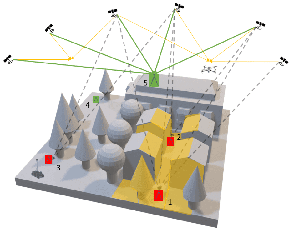
Figure 1. Illustration to demonstrate different possible base station locations in an urban environment
Another factor to consider with selecting your base station location includes the safety and security of the area you’re working in. It must be safe enough to leave a base station (an expensive and important piece of equipment) to run unmonitored for several hours. Referring to the figure above, the clear choice should be (5) – on top of the building, clear of all obstacles with a clear line of sight to the satellites. If location (5) is not possible, an open area (4) would be the next best option, as the number of obstacles blocking it are less than (1), (2) and (3).
The distance between the base station and rover is another important factor to consider. Double difference carrier phase processing estimates the errors resulting from the satellite signals as they are perturbed traveling from the satellite through the Earth’s atmosphere (ionosphere and troposphere) to the base station and rover. The processing assumes that the signals propagating from the satellite to the base station experience the same atmospheric conditions as the signals propagating from the satellite to the rover. The greater the distance from the base station to the rover, the more likely there is to be differences in atmospheric conditions. A distance of several kilometers between the rover and base station is acceptable in most cases as the atmosphere is unlikely to differ greatly at these distances.
The example above considers the use of PPK. Complexity is added for applications where RTK is used rather than PPK. For RTK, you have an added requirement for clear line-of-sight from the base station to the rover besides the line-of-sight to satellites. A radio link is needed for this operation and any dropouts in datalink result in problems with the real-time processing. While this initially doesn’t sound like a stumbling block, the challenge becomes more pronounced for ground-based operations (e.g. Geo-MMS installed on a car), as the rover in this case can frequently be affected by obstructions to its clear view to the satellites (e.g. urban areas with high-rise buildings, roads through forested areas, bridges, tunnels etc.). How we handle this issue will be the subject of another blog (forward/backward smoothing filter).
To summarize, consider the scenario in Figure 2 where the UAV is flying low in a valley. Which base station location is best? We hope it is clear that (1) would be better than (2) and (3), due to the elevated height resulting in increased sky visibility and being closer to the area of interest AOI.
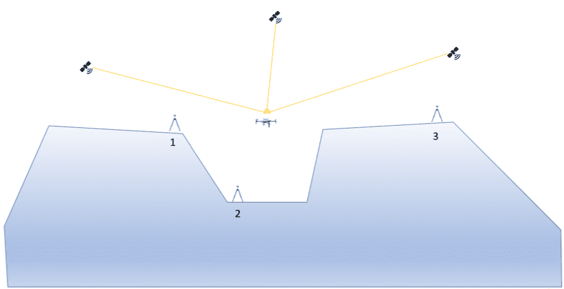
Figure 2. Illustration to demonstrate different possible locations in a rural environment.
Based on the reasoning outlined above, we hope that this relatively straightforward, but critical aspect of your Geo-MMS workflow is taken care of adequately and you can reliably and consistently get strong PPK solutions with the finest absolute accuracies obtainable.
Geodetics offers PPK and RTK compatibility with all our mobile mapping systems to cater to all applications in the air and on the ground. Request more Information to find out how we can assist you in your work. Already have a clear idea regarding your envisaged workflow? Request a Quote today and our team will promptly be in touch.
