Geo-MMS Offers Photogrammetry and LiDAR in One Payload
The FAA Part 107 pilot license has opened the door to a wide range of new drone-based mapping applications that were previously prohibited by regulation. New UAV-mapping technologies are rapidly finding their way into these new markets. When it comes to mapping, recent UAV technologies are designed to use either cameras or LiDAR sensors. UAV photogrammetry is being used for mapping small areas with a minimum budget. All that is required is a drone that can carry a camera and capture images with high overlap/sidelap to cover the area. Processing is then handled by commercial photogrammetry software. Accuracy can be improved using better lenses, flight at altitudes that keep image scale consistent between images or flying with more and/or less overlap/sidelap. Structure from Motion (SfM) has also emerged as a simplified version of photogrammetry that can create a relative 3D model quickly.
Despite the success of low-cost UAV photogrammetry systems, this technology has its challenges. These challenges are categorized as either principal or operational. Principle challenges include low base-to-height-ratios and short parallax that affect vertical resolution/accuracy. UAV photogrammetry also struggles to perform in areas with low-to-no texture such as foliage, canopy, ice fields, flat, deserts, etc. Operational challenges of UAV-Photogrammetry include the time-consuming survey of Ground Control Points (GCP) in and around the area of interest (AOI). Additionally, considering the number of images captured to cover a particular AOI with the up-to 90% overlap/sidelap required by photogrammetry, locating these GCPs throughout the captured images can be a time-consuming effort. The last challenge is processing time, which may take a day or more.
To overcome the operational challenges, Geodetics has introduced its Geo-Photomap solution. Geo-Photomap tightly integrates GPS/IMU data with an onboard camera resulting in direct-georeferencing of the captured images without the need for ground control points and significantly reduced overlap/sidelap requirements. The key in this process is to tightly control camera triggering and accurate time-tagging of the captured images. The Exterior Orientation Parameters (EOP) of the images are interpolated/extrapolated from the GPS/IMU trajectory solution and added to the EXIF image headers. Once this is complete, the time-tagged and geo-tagged images are processed by commercially available photogrammetry packages. An additional advantage of Geo-Photomap is enabling both corridor and vertical mapping without GCPs.
To overcome the principle challenges UAV-Photogrammetry, one approach is to use LiDAR sensors. When comparing photogrammetry vs liDAR Geodetics’ Geo-MMS LiDAR solution is a drone mounted LiDAR mapping payload, which includes a high-performance inertial navigation system coupled with the on-board LiDAR sensor. Raw sensor data are processed in real-time or post-mission using Geodetics’ extensive software suite to provide high-accuracy directly geo-referenced LiDAR point clouds in the LAS format. An advantage of the Geo-MMS LiDAR system is the capability of mapping areas with dense foliage, high canopy, and generating DTM/DSM even in areas with no-to-low texture. Table 1 (below) summarizes the advantages and disadvantages of photogrammetry vs LiDAR technologies. The tradeoff is between system price and processing time.
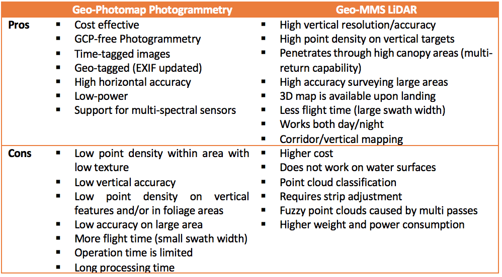
Table 1: Comparison of the Geo-Photomap Photogrammetry vs. LiDAR Mapping
In many mining applications, mapping is needed in near real-time. For example, in open-pit mines, the crane operator needs to know the slope of the mine wall during rock scaling or excavation as he works as shown in Figure 1. In this case, Geo-MMS LiDAR is a good candidate for monitoring and estimating the volume changes. On the other hand, if mapping and change detection process is required less frequently i.e. on daily basis, Geo-Photomap is more appropriate.
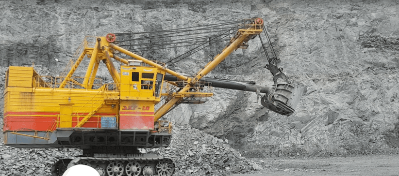
Figure 1: Open-Pit Mine Wall and Slope Detection
To compare system performance, a case study was conducted in which a DJI Matrice 600 Pro drone was equipped with both a camera and LiDAR sensor (Sony A6000 Camera with focal length 16mm and Velodyne VLP-16 LiDAR). More than 20 GCP’s were surveyed in and around the AOI; some were used as the GCP input to the photogrammetry process and some were used as check points. We analyzed the data resulting from the following four approaches:
- Classic UAV-Photogrammetry with high overlap/sidelap and using GCPs for geo-referencing
- UAV-Photogrammetry with geo-tagged images (GCP-free), high overlap/sidelap
- Geo-Photomap (GCP-free) with low sidelap
- Geo-MMS LiDAR (direct-georeferencing point clouds)
Figure 2 shows a summary of flight plans used for each of the four approaches. In the first flight, flight planning was designed for classic UAV-Photogrammetry where a high overlap-sidelap was used to cover the AIO. In this flight, more than 1100 images with time interval of 1sec were collected and fed to commercial photogrammetry software for processing. For geo-referencing, four GCPs on the corners of the AIO were used. Data processing for this configuration took more than one day. For the second approach, the same images were used for the photogrammetry process, but instead of using the GCPs, the images were geo-tagged and used in the Bundle Adjustment with a high accuracy (5cm). The processing time for this configuration was reduced to about one day.
In the second flight, designed for testing the Geo-Photomap approach (#3 above), a sidelap of 30% was used for the separation of the strips. The forward overlap was still set to 80% and we retained the 1sec image time interval. Using this approach, the flight duration was reduced from 20 min required for first fight with 80% overlap/sidelap, to less than 5 min. Additionally, this configuration enabled us to capture the AOI with only 220 images, reducing processing time to several hours. In the last approach, Geo-MMS LiDAR, the data was collected with the LiDAR set to scan a 90° field of view at an altitude of 40m. This flight plan allowed an effective swath width of 80m, which reduced the flight duration to 3 min for the AIO.

Figure 2: Processing with Four Different Approaches
The RMS values on more than 20 check points placed in and around the AIO shows similar accuracies for the first three approaches. Table 2 summarizes the RMS errors of the check points. The Geo-MMS LiDAR RMS error was slightly better than the Geo-Photomap. One suggestion to improve the Geo-Photomap performance is to use a larger lens, e.g., 20mm or higher.
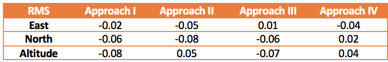
Table 2: RMS Error on Check Points in Four Different Approaches
This test confirms that by using Geo-Photomap with less sidelap and no GCPs, system performance matches the classic photogrammetry approaches but can be achieved with much less processing time. The advantages here are clear. The time-consuming task of setting up and surveying GCP’s is eliminated, the AOI can be covered more quickly and processing time is significantly reduced.
Change Detection and Volume Extraction by Geo-MMS LiDAR
The next test was designed for change detection and volume estimation for the Geo-MMS LiDAR. An active quarry area was surveyed twice with the Geo-MMS LiDAR with a three-day separation between surveys. Figure 3 shows the LiDAR point clouds of the area on both surveys. As can be seen, many new stock materials were added to the field and the goal was to estimate the volume of the new stock. For this purpose, two geo-referenced point clouds were used. Figure 4 shows the overall process performed. As shown in Figure 4, change detection between two geo-referenced LiDAR point clouds showed the volume difference between two surfaces in a very short time.
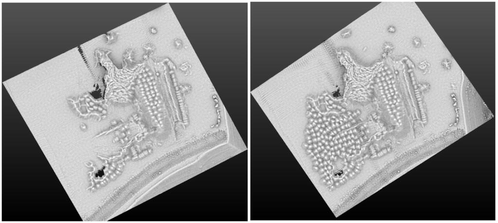
Figure 3: Geo-MMS LiDAR Mapping on an Quarry in Two Different Days

Figure 4: Volume Extraction between Two Datasets
Interested in learning about what Geo-MMS product would be best for your project or more about photogrammetry vs LiDAR request more information today!
