Geodetics Supports Map Coordinates in LiDAR Mapping Accuracy
In drone-based LiDAR mapping accuracy, the drone’s trajectory used in georeferencing the LiDAR mapping point cloud, is typically computed in the WGS84 coordinate datum. This can be further represented in three frames based on the WGS84 datum. This includes: (1) Earth-Centered, Earth-Fixed (ECEF) XYZ, (2) geographic Latitude/Longitude/Altitude coordinate system (LLA), and (3) local navigation frame (North, East, Up).
Theoretically, from the ECEF and LLA coordinate frames, one can transfer the coordinate frame to any other datum, coordinate, and projection system.
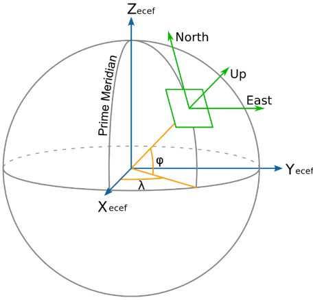
Figure 1: Standard 3D Coordinate Frame
The projected coordinate system is defined on a flat, 2D surface. The difference between a geographic coordinate system (ECEF, LLA) and a projection coordinate frame is that projected coordinate systems are based on a plane, cone, or cylinder (the spheroid projected onto a 2D surface). Linear units are also leveraged (feet, meters, etc.), as shown in Figure 2.
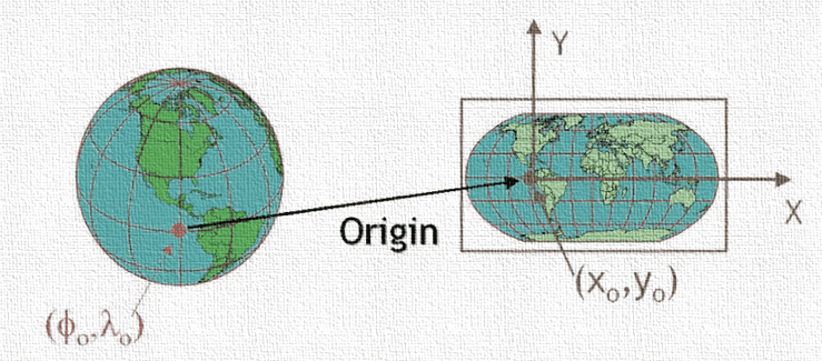
Figure 2: Projection Coordinate Frame (2D)
In addition to 2D coordinate frames, a vertical datum is required to provide a 3D coordinate frame for any projection coordinate system. The vertical datum is usually represented as either height above ellipsoid (ellipsoid height) or mean-sea-level (orthometric height), shown in Figure 3.
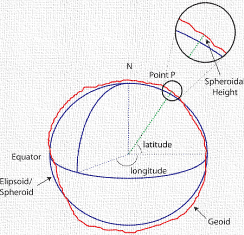
Figure 3: Vertical Datum- Ellipsoid Altitude vs. Geoid Altitude
The ellipsoidal altitude is the distance from a point on the surface to the ellipsoid (Figure 4). The orthometric height of a point on the Earth surface is the distance from the point to the geoid. The difference between these two altitudes is defined by the geoid height, e.g., N. Geodetics LiDARTool software supports both altitude representations and enables drone-based LiDAR mapping accuracy.
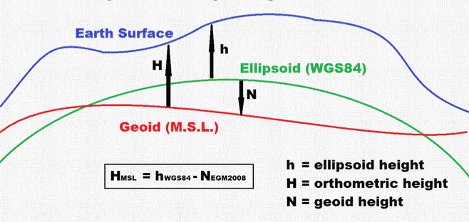
Figure 4: Ellipsoid Altitude and Orthometric Altitude
The vertical datum is more complex then 2D horizontal projection, as there are several different Geoid models in use. The Earth is dynamic and changes its MSL after notable events such as earthquakes, tsunamis, volcanos, etc., causing models to change over time. Using a map that was created in the past, it is likely that map was created with a different geoid model than what is currently in use. To use the map today, we would need the Geoid model used to create that map. The problem gets more complicated when the geoid height is not precisely known for the older map.
This is why the LiDARTool makes several representations available for these complicated scenarios. Two options are offered for orthometric height. The first option employs the Earth Gravitational Model 1996 (egm96) to transfer the altitude (the latest model). With this model one can use the option of “Orthometric-model”; otherwise, you can pick the option of “Orthometric-fixed” (Figure 5). This option allows users to apply their own shift to the altitude.
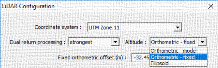
Figure 5: Altitude Options in the LiDARTool
There are hundreds of projection coordinate frames in existence. For example, in the US there are more than 150 State Plane coordinate systems, each associated with different geoid model or ellipsoid datum. Support for many of these has been added to the LiDARTool with additional new coordinate systems being added all the time. If the desired coordinate frame is not present in the current LiDARTool menu, contact Geodetics to have it added to the system. In the meantime, LLA and ECEF XYZ are still available for use in commercial software products to allow users to convert to their desired coordinate frame.
Many commercial GIS software packages support 3D to 2D projection transformations. However, this application is often cumbersome and lacks integration into the workflow. At Geodetics, we promote “One Click” processing methodology as we have streamlined the workflow related to these transformations and made them an integral part of our LiDARTool software.

Figure 6: Supporting coordinate frame inside the “One-Click” LiDARTool software
To learn more about Geodetics LiDARTool software and LiDAR mapping accuracy request more information today!
